As with pretty much all of my layouts, the plan simply "grew" as I went along. I had a few ideas of what I wanted and how I wanted to operate, and started building to suit.
In this post, I present the schematic for Robson Landing, which is built along the wall to the left of the stairs. The connection to the Salmon Run section of the layout is via the trackage labelled "to Salmon Run", where the drop-in bridge connects both parts of the layout.
The section itself is 15 feet long by 21 inches deep. The shape is irregular due to a jag in the wall, which is covered, at track level by Peterson Tools, a false front building with two sides.
Benchwork is a simple 1x4 lumber grid covered with 1/2 plywood. Metal brackets bolted to the wall, and two strategically-placed legs give it ample support. The top of the benchwork is 45 inches from the floor, a comfortable height to work on and operate with. There is room underneath the benchwork for my work table, and shelving for my modelling tools and supplies.
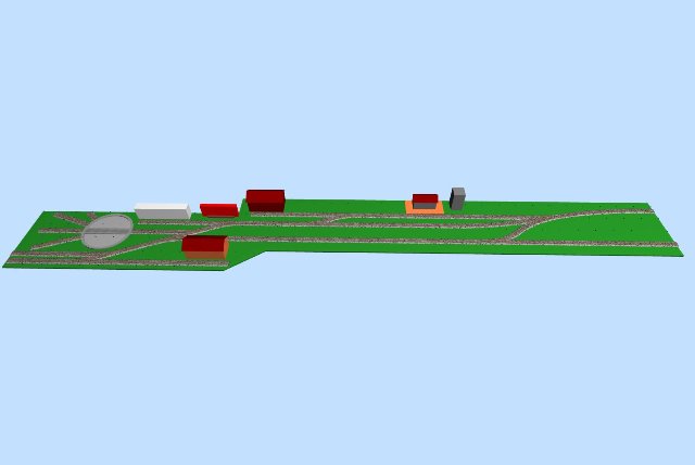
The plan below is pretty much to scale, drawn using the free SCARM - Simple Computer Aided Railway Modeller software, as is the 3D rendering of the section
A future post will describe the Salmon Run section of the layout


No comments:
Post a Comment